The Utilities Window contains shortcuts to various helper functions within ArtiCAD. It is available within all room systems. However the selection of helpers under the "Useful Wizards" button is slightly different for each room system.
If the Utilities Window is not visible, click "Windows" - "Utilities". If the window is present when you exit ArtiCAD, it will be there when you next start ArtiCAD.
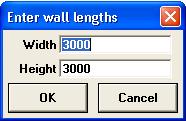
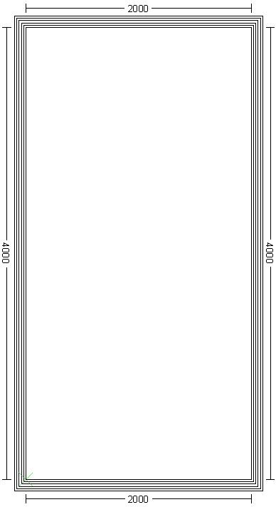
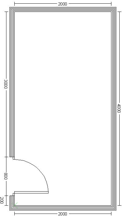
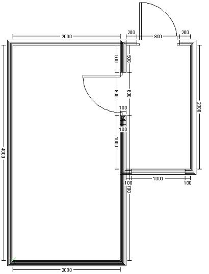
Creates a room outline using the specified width and depth. All other values as per defaults under "This Design" - "Room Settings".
Usage:
Example 1.
A room outline - width 2000, height 4000.
Back to top.
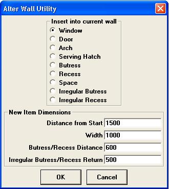
Allows you to insert wall components (doors, windows etc) into an existing run of wall. Allows you to specify the width of the new wall component, but all other values (hinging, style, height off ground) are left as defaults. You may then edit the newly created component once it has been inserted into the wall.
Usage:
Example 1
A door is added to the left-most wall. 200 from the start of the wall. Width 800. Leave the buttress/recess values as default - they will not be used.
Example 2
A buttress is added to the section of wall following the door. 500 from the start. 1500 wide. 300 buttress distance (as it's a regular buttress, no need to specify the irregular value - leave as default).
Back to top.
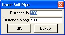
Creates a soil pipe or boxing section in the corner of the room.
Usage:
Example 1
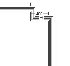
Soil pipe added, 200 in/deep, 400 along/wide.
Back to top.
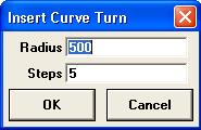
Takes an existing square corner and replaces it with a curved wall. To create anything other than a 90 degree curve, see Drawing the room - Round Wall.
Usage:
Example 1
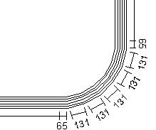
Curved corner added, radius 1500, number of steps 5.
Back to top.
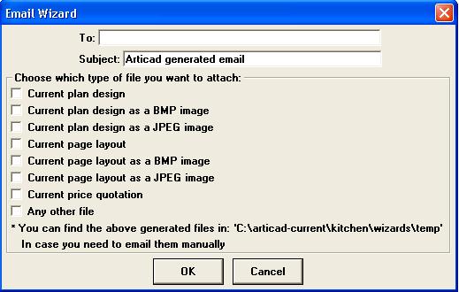
Creates an email with with files automatically attached.
NOTE - Only works with a correctly configured Outlook or Outlook Express email client. Does not work with Hotmail, Google Mail or any other web based system. If you use one of these web-based systems, see Creating Page Layouts.
NOTE - only send "Current Plan Design" to another ArtiCAD user. Only send images (BMP or JPEG) to non-ArtiCAD users.
Usage:
Back to top.
Changes from Normal Mode to Drag and Drop mode. Equivalent to clicking "Mode" - "Drag and Drop". If pressed whilst already in Drag and Drop mode, the plan is zoomed to fit the screen. See Drag and Drop for further details.
Back to top.
Changes from Drag and Drop mode to Normal Mode. Equivalent to clicking "Mode" - "Normal". Normal mode is usually used when creating the Walls layer in your design.
Back to top.
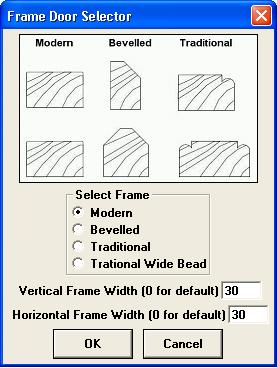
Changes the way doors are drawn on the cabinets in your design from plant-on to in-frame and allows you specify the style of frame and the frame thickness.
NOTE - This can be applied to any door range you have installed.
Usage:
Example 1.

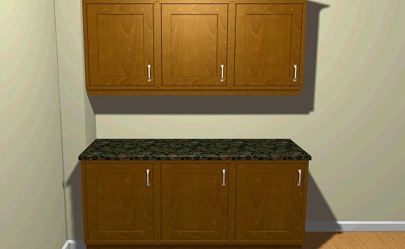
Left-hand image without frame, right-hand image has a modern frame, 30 wide horizontally and vertically.
Back to top.
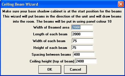
Creates a series of regularly spaced ceiling beams.
Use the multiple select feature of Drag and Drop to move them into place.
Back to top.
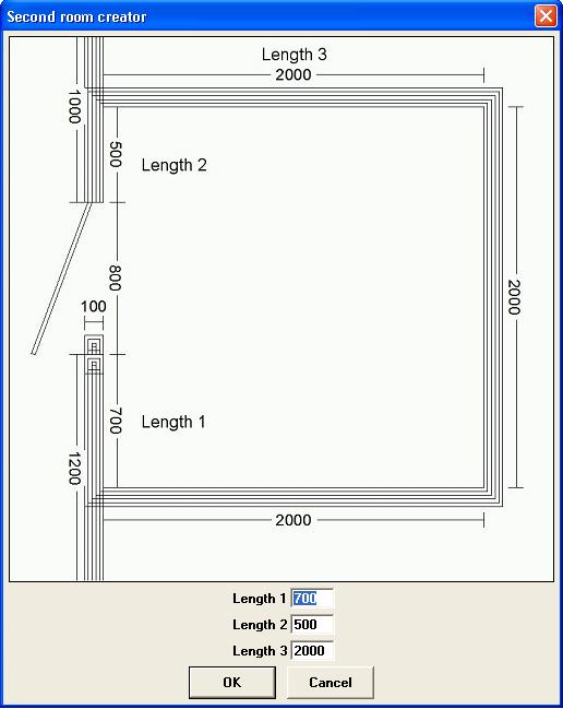
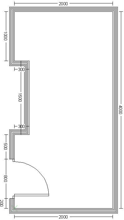
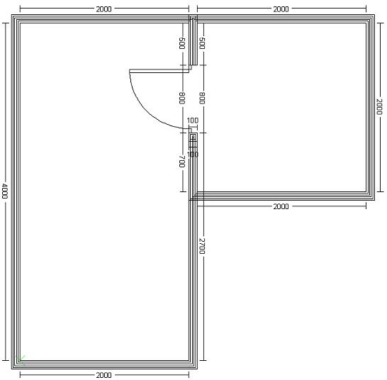
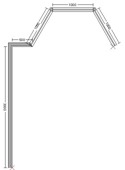
Adds another room onto the walls layer.
ArtiCAD is a room design system i.e. it is intended to design one room at a time. However, it is possible to add a second room onto your plan using this wizard. It is intended for creating utility rooms or en-suites. The new room will use the same wall, wall tile and floor colour as the original room - it is possible to change the wall and wall tile colour by editing the individual wall components. You can also use the Wall Helper to add in extra wall components to the second room.
usage:
Example 1.
Using the default values.
Example 2.
Length 1 = 1000, Length 2 = 500, Length 3 = 1200. Door and window added using Wall Helper.
Back to top.
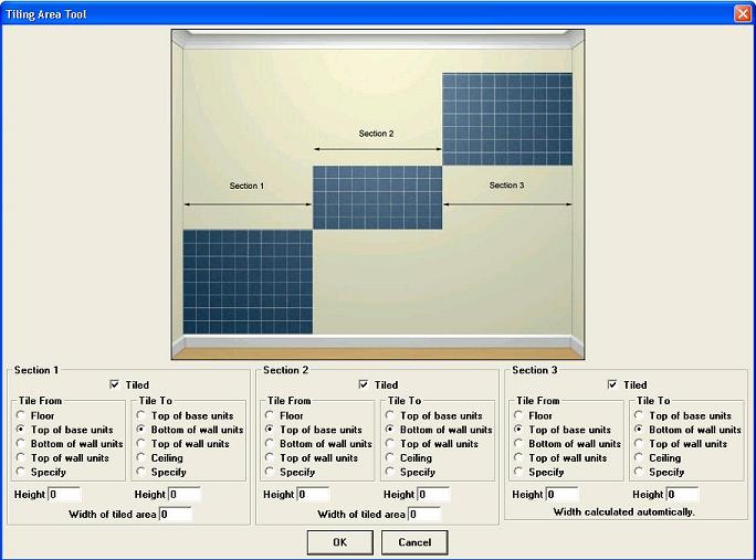
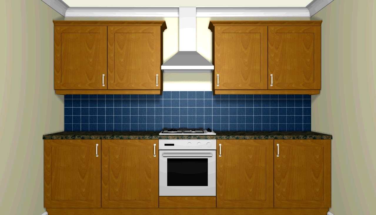
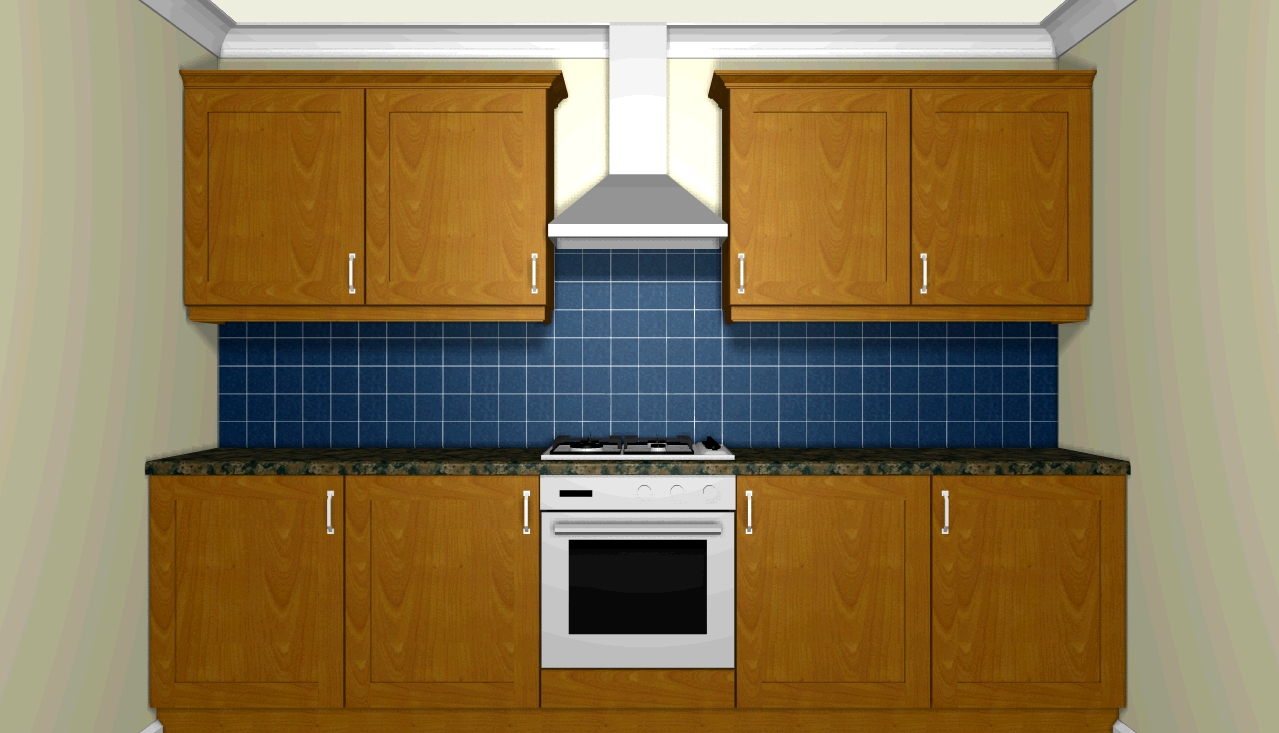
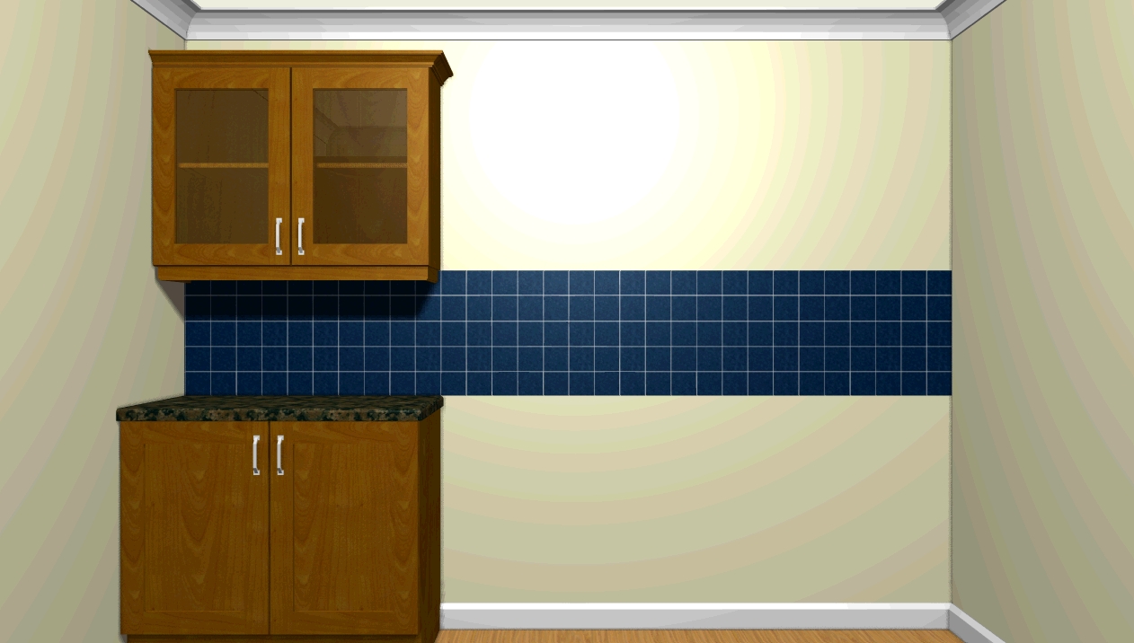
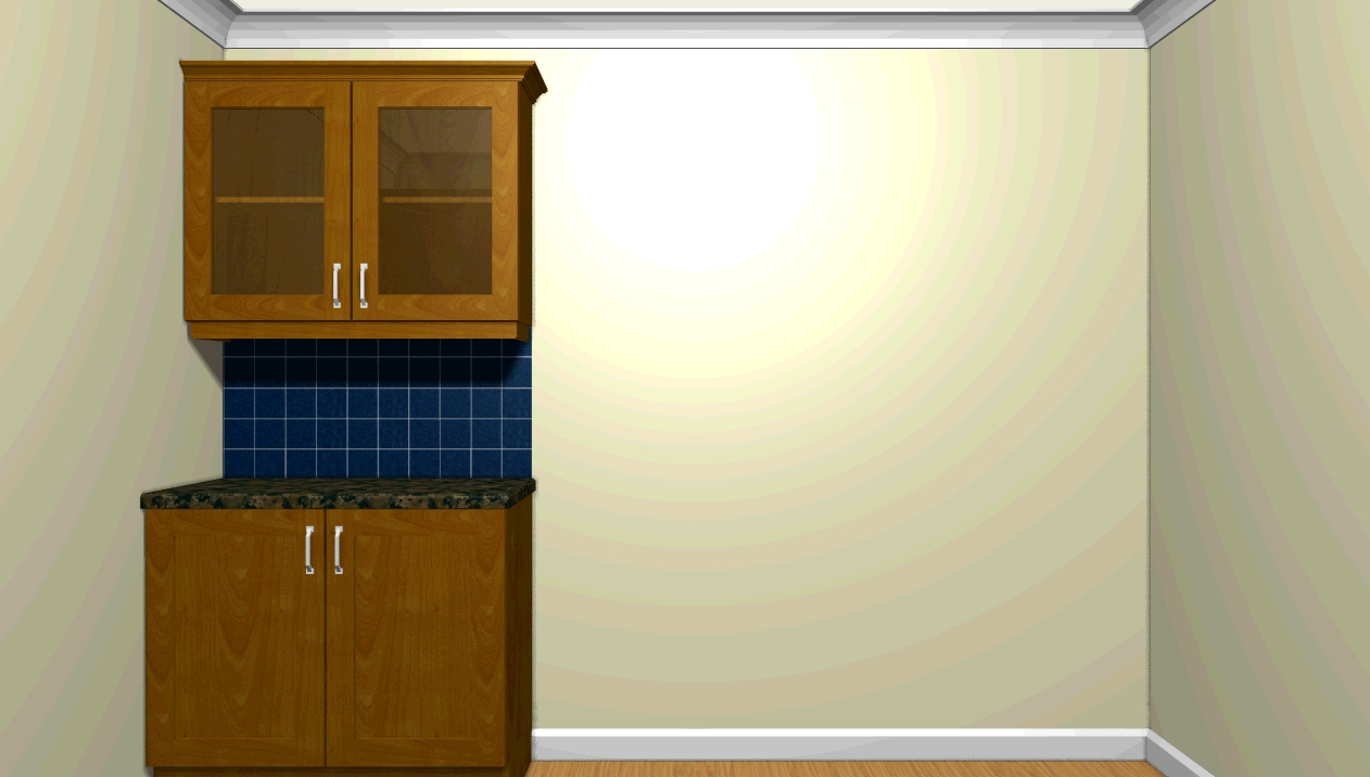
Allows you to alter the tiling on a section of wall.
Turning the tiling on for a section of wall will tile the entire width of that wall section using the same tile from/to values. If you want to have different tiling heights on a wall section (e.g. below a chimney hood) or to stop the run of tiles in line with the end of a run of units, use this wizard.
Usage:
Example 1
Example 2
Back to top.
Calculates the area of tiling specified in your design and the total floor area.
NOTE - does not take into account whether a tiled area is behind a unit. It is the tiled area specified, not the tiled area that is visible. Same applies for the floor area. Figures should be used as a guide only.
Usage:
Example 1
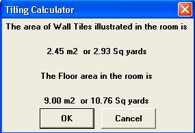
Total tiling and floor area.
Back to top.
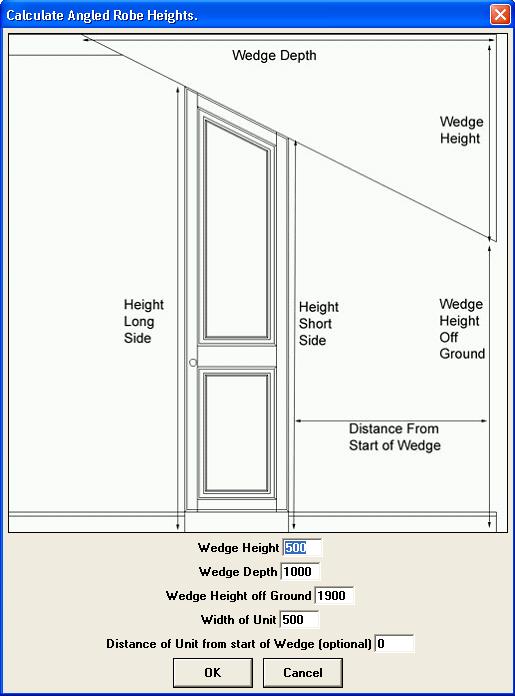
Calculates the heights of the left and right sides of an Angled Cut Wardrobe so it fits under a sloped ceiling.
Usage:
Example 1
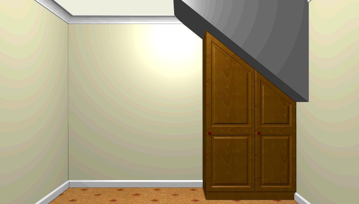
Wedge dimensions - Height off ground = 1200, Depth = 1500, Height = 1200. The Width is 1000, but is not needed for this wizard.
For the right-hand robe, the distance from start of wedge = 0. The robe is 500 wide. The results from the wizard are 1200 for the short side and 1600 for the tall. When creating the Angled Cut Robe, the short side will be the right-hand side, so set the "Height of right-hand side" to 1200. Set the "Height" to 1600.
For the left-hand robe, the distance from start of wedge = 500 (i.e. the width of the right-hand unit). The robe is 600 wide. The results from the wizard are 1600 for the short side and 2080 for the tall. Set the "Height of right-hand side" to 1600 and the "Height" to 2080.
Back to top.
To run the wizard, click "File" - "Run wizard..." or press "Control"/"Ctrl" and "W" on your keyboard.
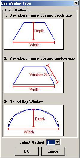
There are three ways of specifying the dimensions of the bay window. Select the method using the drop-down box at the bottom of the dialog.
Draw you room up to the point where the bay would start.
Run the wizard as described above. Choose the method appropriate to the room layout.
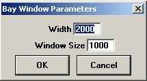
The above image shows the options for method 2. Change to the required values and click "OK" to add teh bay onto your design.
Continue drawing the rest of your room as normal.
Return to top.